

Sign In Join Free


1 / 5
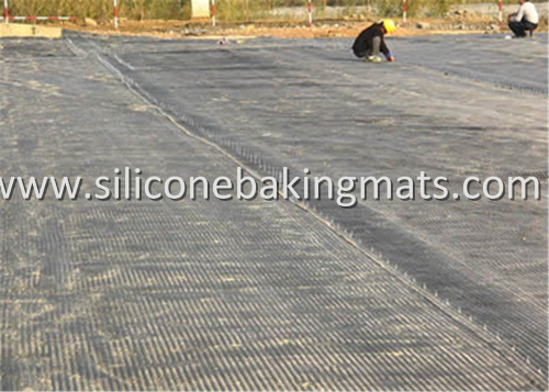
Unaxial PET geogrid Retaining Walls & Slope Reinforcement
| Model No. : | PET9030 |
|---|---|
| Brand Name : | Fibtex |
| Material : | High Tenacity Polyester Yarn + SBR Or PVC |
Yangzhou, Jiangsu, China
- Manufacturer
- OEM service
- Platform Certification

- SGS Certification

- Video


Product description
Unaxial PET geogrid Retaining Walls & Slope Reinforcement is warp knitted by high tenacity multi-filament polyester yarns with various mesh sizes and tensile strength from 20 to 1000kN/m. Exterior of Unaxial PET Geogrid coated with PVC or modified polymer mixture for UV, acid and alkali resistance prevents the bio-decomposition. Unaxial PET Geogrid For Retaining Walls are a precision grid that offers superior junction strength and high coefficient of soil interaction. Uniaxial PET Geogrid for Slope Reinforcement is a perfect choice for steep slope stabilization.
Certificate: ISO9002, CE, ITB
Features and Benefits
- High tensile force at low elongation
- High ultimate tensile strength
- Excellent long-term behaviour due to low creep characteristics
- High resistance to soil micro-organisms and chemicals, UV radiation and mechanical damage
- Good grid/soil interaction provided by selecting the geogrid mesh to accommodate the adjacent material
- Problem-free installation due to low product weight and excellent flexibility even in extreme cold
- Very wide range of tensile strengths in length and width
Applications
- Load-bearing layers in road, railway and airport construction
- Access roads and transportation routes
- Retaining walls and extra-steep earthwork slopes
- Slope stabilisation
- Noise reduction barriers
- Reclamation of industrial wasteland
- Earth embankments over piles
- Landfill
- Bridging of underground voids or sinkholes
Technical Data
Type
Item No.
Tensile Strength
Elongation
Mesh Size
Width
MD
CD
(%)
(mm*mm)
(m)
Polyester Uniaxial
Geogrid
PET5030
30
30
13
12-50
1-6
PET6030
60
30
13
12-50
1-6
PET8030
80
30
13
12-50
1-6
PET10030
100
30
13
12-50
1-6
PET11030
110
30
13
12-50
1-6
PET120/30
120
30
13
12-50
1-6
PET15030
150
30
13
12-50
1-6
PET20030
200
30
13
12-50
1-6
PET30030
300
30
13
12-50
1-6
PET40050
400
50
13
12-50
1-6
PET50050
500
50
13
12-50
1-6
PET60050
600
50
13
12-50
1-6
PET80050
800
50
13
12-50
1-6
Polyester
Biaxial
Geogrid
PET3030
30
30
13
12-50
1-6
PET4040
40
40
13
12-50
1-6
PET5050
50
50
13
12-50
1-6
PET6060
60
60
13
12-50
1-6
PET8080
80
80
13
12-50
1-6
PET9090
90
90
13
12-50
1-6
PET100100
100
100
13
12-50
1-6
PET110110
110
110
13
12-50
1-6
PET120120
120
120
13
12-50
1-6
PET150150
150
150
13
12-50
1-6
PET180180
180
180
13
12-50
1-6
PET200200
200
200
13
12-50
1-6
PET300300
300
300
13
12-50
1-6
PET350350
350
350
13
12-50
1-6
PET400400
400
400
13
12-50
1-6
PET450450
450
450
13
12-50
1-6
PET500500
500
500
13
12-50
1-6
PET600600
600
600
13
12-50
1-6
PET700700
700
700
13
12-50
1-6
PET800800
800
800
13
12-50
1-6
(kN/m)


Packages
Wound by Cardboard ot PVC tube, then wrapped by PE film or polybag.

How to install Polyester Geogrid
Step 1:Excavate reinforced soil area.
Remove existing soils in the reinforced soil area to the maximum embedment length of the geogrid design. Provide a generally level soil condition behind the wall units for the placement of each geogrid layer.
Step 2: Cut Geogrid.
Cut sections from geogrid roll to the specified length (embedment depth). Geo-grid roll direction is from the wall toward the embankment (check manufacturer's criteria). In most cases correct orientation is to roll the geogrid perpendicular to the wall face.
Step 3: Install Geogrid.
Hook geogrid over the fiberglass pins to ensure a positive mechanical connection between the unit and geogrid
Step 4: Secure Geogrid.
Pull the pinned geogrid taut to eliminate loose folds. Stake or secure back edge of geo-grid before and during backfill and compaction. Remove stakes, if desired, once backfill is placed. Place additional sections of geogrid, abutting each other, for continuous coverage at each layer.
Step 5: Install next course of units.
Check for level with each new course.
Step 6: Place compacted backfill over geogrid in 8" lifts.
Provide a minimum of six inches reinforced fill coverage prior to driving equipment over the geogrid with wheeled or tracked equipment. Avoid driving or turning equipment directly on geogrid to avoid excessive damage.

Yangzhou, Jiangsu, China
- Manufacturer
- OEM service
- Platform Certification
- SGS Certification
- Video
Send your inquiry to this supplier
Product Alert
Subscribe to your interested keywords. We will send freely the latest and hottest products to your Inbox. Don't miss any trade information.
Your use of this website constitutes acknowledgement and acceptance of our Terms & Conditions.
Copyright © 2009-2024 Bossgoo Co., Ltd. All rights reserved.
