

Sign In Join Free

1 / 1
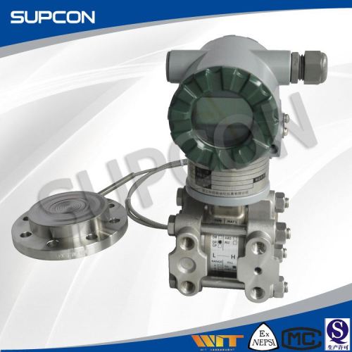
Stable performance factory directly 4-20ma strain gauge pressure transmitter
| Model No. : | SKW Small Flange Remote Seal Type Pressure Transmitter |
|---|---|
| Brand Name : | SUPCON |


Product description


| Features | ||||||||||
| 1 | Directly connectable to 1½in and 2in flanges | |||||||||
| 2 | Minimum environmental influence | |||||||||
| 3 | Application flexibility – High temperature, high vacuum seals | |||||||||
| Specifications | ||||||||||
| 1 | Span, range SKW 5 4000 40000 the filled fluid 40000 60 | |||||||||
| 2 | Work pressure | |||||||||
| 3 | Process temperature, Lower range limit Silicone oil Y, G (-40~180)℃ 2.7kPa abs Silicone oil S (-15~250)℃ 2.7kPa abs | |||||||||
| 4 | Performance Specifications for Linear Output Accuracy rating (including linearity, hysteresis, and repeatability) | |||||||||
| 5 | Physical Specifications Process-wetted parts material | |||||||||
| Item Name | SKWEN Small Flange Remote Seal Type Pressure Transmitter |
| Material | Metal |
| Size | L121*W94*H190cm |
| Color | silver and atrovirens |
| Process | Casting,Stamping,Polishing,Filling Silicon Oil, Painting, Assembly, Calibrating, Packaging |
| Custom Desigh | Welcome |
| Service | OEM&ODM |
| MOQ | 1pcs |
| Sample | Available |
| Sample Cost,The cost will be returned after placing an order | USD1100 |
| Sample Lead Time | 7-15 Days |
| Payment Terms | T/T, LC at sight,west union,paypal |
| Packing | carton package with protection material |
| Production Time | 15-30 Days |
| Delivery Port | Ningbo or Shanghai |


 Q: Are you a manufacture or a trading company? A: We are a 20-year-manufacturer engaged in the field of cleaning products, and we have got the permit of import and export as well. Q: Where is your factory located? How can I visit there? A: Our factory is located in Hangzhou, China. 25 Minutes by car far away from Xiaoshan Airport. Q: How can I get the Stable performance factory directly 4-20ma strain gauge pressure transmitter samples? What's the lead time? A: Samples could be sent within one week, the lead time is 35-45 days.. Q: Do you provide Stable performance factory directly 4-20ma strain gauge pressure transmitter ODM/OEM service? A: OEM/ODM is welcome, there are 25 persons in our R&D team, and customized colours is optional. From the concept to finished goods, we do all (design, prototype reviewing, tooling and production) in the factory.
Send your inquiry to this supplier
Product Alert
Subscribe to your interested keywords. We will send freely the latest and hottest products to your Inbox. Don't miss any trade information.
Your use of this website constitutes acknowledgement and acceptance of our Terms & Conditions.
Copyright © 2009-2024 Bossgoo Co., Ltd. All rights reserved.
