

Sign In Join Free


1 / 5
Led display receiving card A7 Model
| Model No. : | Novastar receiving card A7 Model |
|---|---|
| Brand Name : | OEM |
Shenzhen, Guangdong, China
- Manufacturer
- OEM service
- Platform Certification

- Online Expo

- The Belt And Road


Product description
Led display receiving card A7 Model
Product Feature:Led display receiving card A7 Model
Features
Description
Supporting pixel level brightness
and chroma calibration
Working with NovaLCT and NovaCLB,
A7 supports brightness and chroma calibration on each pixel.
Supporting image rotation in 90° increments
(Calibration not supported after
rotation)
On NovaLCT, the image on the
screen can be set to rotate in the multiples of 90° (90°, 180°, 270° and 360°).
Supporting quick seam correction
Working with NovaLCT, A7 supports
quick adjustment of bright and dark lines, which can remove the seams between
modules and between cabinets.
Supporting 3D function
On NovaLCT or operation panel of
controllers which support 3D function, you can enable 3D function and set the
3D parameters to make the LED screen display 3D effects.
3.2 Improvement in Maintainability
Features
Description
Supporting the smart module
(Supported by dedicated firmware
program)
The smart module is composed of
Flash and MCU.
Flash could store calibration
coefficients and module information. MCU could communicate with the receiving
card to realize monitoring over temperature, voltage and wiring communication
status for the module. Working with the driver chip, A7 supports open circuit
detection on LED.
The smart module could make
monitoring unit smaller, requiring no independent monitoring card
Receiving Card A7
Features
Description
and saving cabinet space.
Supporting LVDS transmission
(Supported by dedicated firmware
program)
The transmission mode of
low-voltage differential signaling (LVDS) is used, which reduces the number
of data cables that connect the receiving card's HUB board to the module,
increases the transmission distance, improves the signal transmission
quality, and better stabilizes the image output.
Supporting auto module calibration
After the module has been
replaced, the receiving card can automatically read the new module ID and
calibration coefficient which could be saved to calibration system files.
Supporting Mapping function
Enable the Mapping function on
NovaLCT, then the target cabinet will display the cabinet number and Ethernet
port information, and the user could get the receiving card`s location and wiring route.
Supporting setting of images
pre-stored of the receiving card
On NovaLCT, the specified images
could be set as the screen startup image and images used when the Ethernet
cable is disconnected or no video source signal is available.
Supporting module Flash management
On NovaLCT, lamp panel Flash could
be managed.
Supporting monitoring voltage and
temperature of itself
The voltage and temperature of the
receiving card itself can be monitored without using other peripherals. The
monitoring data can be checked on NovaLCT.
Supporting LCD module
Supports NovaStar's general 5-pin
LCD module. The LCD module is connected to the HUB board to display
temperature, voltage, single operating time and total operating time of the
receiving card.
Support one-click application of
calibration coefficient in module Flash
In the event of network outage,
hold down the self- test button to read the calibration coefficient in module
Flash back to the receiving card.
3.3 Improvement in Hardware
Reliability
Features
Description
Supporting dual-card backup
In the high-reliability
environment, single HUB board could be populated with two A7 receiving cards.
In case that the main receiving card fails, the standby one will serve in a
timely manner to ensure normal operation of the display.
Supporting dual-power
Two power supplies could be
simultaneously
Receiving Card A7
Features
Description
backup detection
connected, and operating status of
the power supplies could be detected.
Supporting loop backup
HUB`s Ethernet port improves the
reliability for the serial connection of the receiving card through main and
standby redundant mechanism. Among the main and standby serial connection
lines, if one fails, the other will begin to work to ensure the normal
operation of the display.
3.4 Improvement in Software
Reliability
Features
Description
Supporting readback of firmware
version
On NovaLCT, the firmware versions
of the receiving card can be read back.
Supporting dual-backup and restoring
of the calibration coefficient
Calibration coefficients could be
saved to both the factory area and application area at the same time.
Calibration coefficients in the
factory area is default as the delivery value, while the calibration coefficient
in the application area could be modified or be restored to the factory reset
by the user on NovaLCT.
Specifications 3
Features
Specifications 3
Features
|
Product Image |


|
Product Parameters |
|
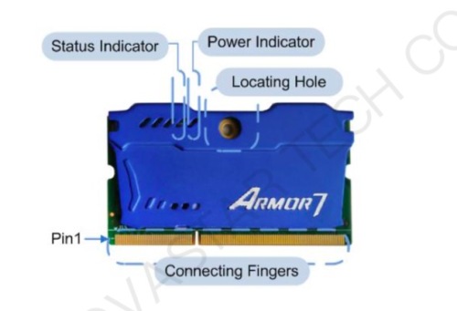
Receiving Card A7 Unit of the dimension chart is [mm". Ground connection is enabled for location hole (GND). 4.3 Indicators
Receiving Card A7 4.4 Definition of Data Interface ( Top ) 4.4.1 32-Group Parallel Data
Receiving Card A7 Specifications
Receiving Card A7 4.4.2 64-Group Serial Data
Receiving Card A7 Specifications Note 1. Voltage ranging from 3.3V to 5.5V is recommended for input power (VCC). 4.4.3 Extended Functions Design Expandable Interface RFU1 RFU2 Recommended Smart Module Interface Reserved Reserved Recommended Module Flash Interface Reserved Reserved Description Reserved pin connected to MCU Reserved pin connected to MCU www.novastar.tech 13 GND 143 144 GND NC 145 146 NC NC 147 148 NC NC 149 150 NC NC 151 152 NC NC 153 154 NC NC 155 156 NC NC 157 158 NC NC 159 160 NC GND 161 162 GND NC 163 164 NC NC 165 166 NC NC 167 168 NC NC 169 170 NC NC 171 172 NC NC 173 174 NC NC 175 176 NC NC 177 178 NC GND 179 180 GND NC 197 198 NC VCC 199 200 VCC VCC 201 202 VCC VCC 203 204 VCC Note2. Operatingindicatorthatmeetslowlevelisvalid. Note 3. OE_RED, OE_GREEN and OE_BLUE are display enabled pins. In case that OE_RGB are not controlled separately, OE_RED is applied. While PWM chip is used, GCLK signal is enabled. Note 4. RFU1–18 are the reserved extended function interfaces. Please refer to [4.4.3 Extended Functions Design". Extended Functions Description
Receiving Card A7
Note: The RFU8 and RFU10 are signal multiplex extension interfaces. You can select only one interface from either the Recommended Smart Module Interface or the Recommended Module Flash Interface at the same time. Receiving Card A7 Specifications Step 1 Step 2 Step 3 Step 4 Step 5 5 Firmware Update 5 Firmware Update Visit www.novastar.tech to download the firmware update package and save it to PC. Run NovaLCT and choose User > Advanced Synchronous System User Login to
log in. Click Browse to select the program (the firmware update package you saved on PC) path and then click Update. Click Refresh to check current hardware version information. Receiving Card A7 Specifications 6 Applications 6 Applications A7 is applied to LED display synchronous system which is generally composed of the LED display, HUB board, receiving card, video controller and controller peripheral. The receiving card is connected to the display over a HUB board. Synchronous system requires connecting a computer to display the computer`s images and texts on the LED screen. Structure of the synchronous system is as shown in the following figure.
Receiving Card A7 7 Specifications
www.novastar.tech 17
|
||||||||||||||||||||||||||||||||||||||||||||||||||||||||||||||||||||||||||||||||||||||||||||||||||||||||||||||||||||||||||||||||||||||||||||||||||||||||||||||||||||||||||||||||||||||||||||||||||||||||||||||||||||||||||||||||||||||||||||||||||||||||||||||||||||||||||||||||||||||||||||||||||||||||||||||||||||||
|
Package case |


|
Our Service |
1. Best price: We can offer you the best competitive price with the same even better quality. Mostly depends on the quantity.
2. Best after sale service: We can response in time if customers have questions about the installation , usage and maintenance ect.
3. Your inquiry will be replied by well-trained and experienced staffs in 24 hours.
4. Top Quality+Reasonable Price+Responsible After Service=Successful & Win
5. Help you design OEM&ODM or any your customized lightings and put into production.
6. Distributorship are offered for your unique design and some our current models
7.Your sales area, ideas of design and all your private information will be well protected
Looking for ideal High Quality Led display receiving card A7 Model Manufacturer & supplier ?
---We have a wide selection at great prices to help you get creative ideas. All the Big Outdoor Advertising Screen are quality guaranteed.
---We are China Original Factory of Led display receiving card A7 Model. If you have any question, please feel free to contact us.
Product Categories : Outdoor Full Color Advertising LED Display, Outdoor Single red Color Advertising LED Display,
Wall hanging LED Display, Showcase LED Display, Cross LED Display, Double sided LED Display,
LED Light box, Fine pixel pitch LED Display, Rental LED Display, LED Curtain Display.
Shenzhen, Guangdong, China
- Manufacturer
- OEM service
- Platform Certification
- Online Expo
- The Belt And Road
Send your inquiry to this supplier
Product Alert
Subscribe to your interested keywords. We will send freely the latest and hottest products to your Inbox. Don't miss any trade information.
Your use of this website constitutes acknowledgement and acceptance of our Terms & Conditions.
Copyright © 2009-2024 Bossgoo Co., Ltd. All rights reserved.
