
Search

Sign In Join Free


1 / 6
Hydrographic Surveying Corrosive Liquid Radar Level Sensor
Get Latest Price
Send Inquiry
| Model No. : | VRPWRD93H |
|---|---|
| Brand Name : | V-RIVER |
Dandong Virtue River Technology Co., Ltd.
You might also like


Product description
Product description VRPWRD90 series transmitters are 26GHz high-frequency radar level transmitters with analog signals 4-20mA, the maximal measuring range is up to 70m. The antenna has been further optimized, and the latest update microprocessor can make higher speed signals analysis, which enables the level transmitters can be used in very complicated measuring applications. Working principle The radar level transmitter antenna emits narrower micro wave pulses which will be transmitted via the antenna. The micro wave will be reflected back after touching the surface of a medium, and then antenna system will receive it and transmit it into the electrical circuit, which will be automatically turned into the level signals. Features The radar level transmitter adapts the emitting frequency of 26GHz, therefore it has the following features: Noncontact measuring, no abrasion, no contamination Easy installation due to small size of antenna Smaller beam angle, which makes the energy be more concentrated, enhancing the wave reflection ability which can keep signals more powerful to avoid obstacles. Almost unaffected by corrosion and foams. Almost unaffected by changes of steam, changes of temperature, pressure and humidity in the air, or wind strength or direction, etc. Even in heavy dust environment, the transmitter can also receive the real level return wave. High SNR, which can make the instrument to get better performance. Frequency 26GHz is the best option for measuring solid and low dielectric constant medium. VRPWRD93H l Application: it is suitable the water level measurement for rivers, lakes, reservoirs, oceans, etc. Measuring range (maximum): 70m Process connection: thread, flange, material will be PP or stainless steel Medium temperature: -40℃~+100℃ Process pressure: ATM Accuracy: ±10mm Frequency range: 26GHz Enclosure protection grade: IP67 Signal output: digital signals/RS485/ Modbus Antenna material: stainless steel Power supply: 6 – 24 V DC, or battery, being charged by solar panel on request. Indication: LCD with graph and buttons, with which calibration will be done easier at the site. Back light is available on request. Wiring Power supply and the Modbus signal wire are separate; each has one 2-wire shielded cable. See the technical data for the actual power supply voltage. Cable General introduction
 Cable OD: 5 ~ 9mm (M20 x 1.5) 3.5mm ~ 8.7mm (½NPT) 2-wire or 4-wire cables are used for the electric connection. Due to the electromagnetic interference from the motor drive device, power supply wires or remission devices, the transmitter wires need to be the shielded cable. Shielded wire and ground wire of the cable Ideally the two ends of shielded wire should be connected the ground. But note that: there will be the grounding compensation current passing through the shielded wire. A grounding electric capacity (e.g. 1µF: 1500V) can be connected to one end (e.g. switch cabinet) when the both ends are connected to the ground. Try to use a resistance with much possible lower value to be connected to the ground. 24V, RS485/ Modbus Enclosure protection grade
 This instrument is in fully conformity with the requirements of the enclosure protection grade IP67. Please make sure the waterproof performance of the cable entry seal. See the picture on the right: How to make sure the installation can meet the requirements of IP67: Please make sure the cable entry seal is not damaged. Please make sure the cable is not damaged. Please make sure the cable meets the requirements of the electrical connection regulations. Bend the cable down before entering the electrical inlet, which will keep the water away from the housing, see mark (1) at the above picture. Please tighten the cable entry seal, see mark (2) at the above picture. Please tighten the unused cable entry with a seal cap. See mark (3) at the picture. Transmitter calibration Methods of debugging There are three debugging methods for VRPWRD90: (1). With display/ buttons (2). With a PC with a software (3). With a HART hand-hold communicator Display/ button: Debugging can be done with the 4 buttons on the display screen.
 Menu language is optional. After debugging, the display keeps the normal working condition. The measured values can be clearly read through the glass screen. Display/button (1). LCD display (2). Buttons (3). Wiring terminal Debugging with a PC with a software
 Connect a PC with a HART modem (1). RS232 interface or USD interface (2). VRPWRD9X (3). HART adapter (4). A resistance of 250Ω HART hand-hold communicator
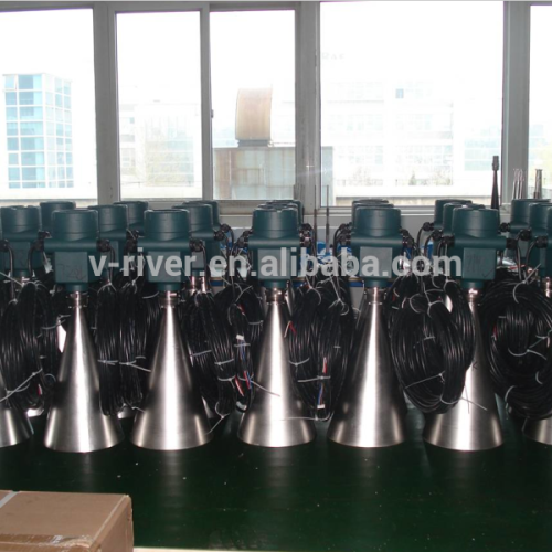
 VRPWRD90 radars can be calibrated with a HART hand-hold communicator. (1). A HART hand-hold communicator (2).VRPWRD90 (3). A resistance of 250Ω Samples Showeroom
 Product Use

 l Application: it is suitable the water level measurement for rivers, lakes, reservoirs, oceans, etc. Measuring range (maximum): 70m Process connection: thread, flange, material will be PP or stainless steel Medium temperature: -40℃~+100℃ Process pressure: ATM Accuracy: ±10mm Frequency range: 26GHz Enclosure protection grade: IP67 Signal output: digital signals/RS485/ Modbus Antenna material: stainless steel Power supply: 6 – 24 V DC, or battery, being charged by solar panel on request. Indication: LCD with graph and buttons, with which calibration will be done easier at the site. Back light is available on request. Wiring Power supply and the Modbus signal wire are separate; each has one 2-wire shielded cable. See the technical data for the actual power supply voltage. Cable General introduction
 Cable OD: 5 ~ 9mm (M20 x 1.5) 3.5mm ~ 8.7mm (½NPT) 2-wire or 4-wire cables are used for the electric connection. Due to the electromagnetic interference from the motor drive device, power supply wires or remission devices, the transmitter wires need to be the shielded cable. Shielded wire and ground wire of the cable Ideally the two ends of shielded wire should be connected the ground. But note that: there will be the grounding compensation current passing through the shielded wire. A grounding electric capacity (e.g. 1µF: 1500V) can be connected to one end (e.g. switch cabinet) when the both ends are connected to the ground. Try to use a resistance with much possible lower value to be connected to the ground. 24V, RS485/ Modbus Enclosure protection grade
 This instrument is in fully conformity with the requirements of the enclosure protection grade IP67. Please make sure the waterproof performance of the cable entry seal. See the picture on the right: How to make sure the installation can meet the requirements of IP67: Please make sure the cable entry seal is not damaged. Please make sure the cable is not damaged. Please make sure the cable meets the requirements of the electrical connection regulations. Bend the cable down before entering the electrical inlet, which will keep the water away from the housing, see mark (1) at the above picture. Please tighten the cable entry seal, see mark (2) at the above picture. Please tighten the unused cable entry with a seal cap. See mark (3) at the picture. Transmitter calibration Methods of debugging There are three debugging methods for VRPWRD90: (1). With display/ buttons (2). With a PC with a software (3). With a HART hand-hold communicator Display/ button: Debugging can be done with the 4 buttons on the display screen.
 Menu language is optional. After debugging, the display keeps the normal working condition. The measured values can be clearly read through the glass screen. Display/button (1). LCD display (2). Buttons (3). Wiring terminal Debugging with a PC with a software
 Connect a PC with a HART modem (1). RS232 interface or USD interface (2). VRPWRD9X (3). HART adapter (4). A resistance of 250Ω HART hand-hold communicator
 VRPWRD90 radars can be calibrated with a HART hand-hold communicator. (1). A HART hand-hold communicator (2).VRPWRD90 (3). A resistance of 250Ω Samples Showeroom
 Product Use
Send your inquiry to this supplier
Send Inquiry
Product Alert
Subscribe to your interested keywords. We will send freely the latest and hottest products to your Inbox. Don't miss any trade information.
Subscribe
Your use of this website constitutes acknowledgement and acceptance of our Terms & Conditions.
Copyright © 2009-2024 Bossgoo Co., Ltd. All rights reserved.
