

Sign In Join Free


1 / 3
energy saving reactive power factor correction unit TSC
| Model No. : | GBD |
|---|---|
| Brand Name : | CODO |


Product description
 There are difficult and easy things in the world. With joint hands (co-do), everything will become easy. GBD serial dynamic reactive power compensation devices(separate compensation) The details show
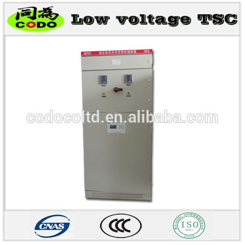
 The BD-type (common compensation) low voltage MNS serial dynamic reactive power compensation devices used in three-phase balanced load delta connection Low BD-type MNS serial dynamic reactive power compensation devices mainly consist of the controller, zero-triggering system, fuse, electric reactor, capacitor, and protection circuit. For the detection of one-phase reactive power (current) with the controller, it will generate the unified controlling signal according to the reactive power (current) on the one-phase, and hence to drive the corresponding electronic switch device to turn to connection or disconnection by triggering the circuit. By this way, through flinging or cutting the same compensation capacitors on a three-phase as per the request to control system power factor within expected range. The single line diagram of working principle is as follows:
|
MNS1-400/X-BD-X series | ||||
No. | Specification and Model | Rated capacity (kvar) | Overall dimension (W×D×H) | Weight (kg) |
1 | MNS1-400/90-BD | 90 | 800×800×2200 | 320 |
2 | MNS1-400/135-BD | 135 | 800×800×2200 | 335 |
3 | MNS1-400/180-BD | 180 | 800×800×2200 | 350 |
4 | MNS1-400/225-BD | 225 | 800×800×2200 | 365 |
5 | MNS1-400/240-BD | 240 | 800×800×2200 | 370 |
6 | MNS1-400/270-BD | 270 | 800×800×2200 | 390 |
7 | MNS1 -400/315-BD | 315 | 800×800×2200 | 470 |
8 | MNS1 -400/360-BD | 360 | 800×800×2200 | 500 |
9 | MNS1 -400/405-BD | 405 | 1000×1000×2200 | 530 |
10 | MNS1 -400/450-BD | 450 | 1000×1000×2200 | 570 |
11 | MNS1 -400/480-BD | 480 | 1000×1000×2200 | 590 |
12 | MNS1 -400/540-BD | 540 | 1000×1000×2200 | 680 |
13 | MNS1 -400/600-BD | 600 | 1000×1000×2200 | 750 |


 Technology
 Heilongjiang province power quality engineering research center at the provincial level The development of advanced testing equipment

Send your inquiry to this supplier
Product Alert
Subscribe to your interested keywords. We will send freely the latest and hottest products to your Inbox. Don't miss any trade information.
Your use of this website constitutes acknowledgement and acceptance of our Terms & Conditions.
Copyright © 2009-2024 Bossgoo Co., Ltd. All rights reserved.
