

Sign In Join Free


1 / 2
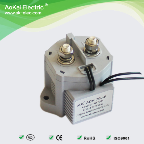
Energy saving high Epoxy Sealant dc relay for Rechargeable batteries 200A 12V 24V Coil voltage dc contactor
| Model No. : | ADH200P |
|---|---|
| Brand Name : | Aokai |


Product description
 Energy saving high Epoxy Sealant dc relay for Rechargeable batteries 200A 12V 24V Coil voltage dc contactor
 | Brand:AK/AoKai
Name:ADH High-voltage DC Contactor
Model:ADH200AP
Rated Voltage:DC12/24/48V
Rated Current:200A,DC12-900V
Dimension:80.0*64.2*78.7(mm)
Weight:About 440g |  |
| Product Features:1,Nonpolarity—The connection of contact and coil need to be nonpolarity;2,Epoxy Sealant—Sealed by epoxy resin. It can work in the hostile environment,Coil and contact cannot be oxidized and polluted;3,Efficient Coil - Optional built-in energy-saving coil, retentive power is only 2-2.3W, counter electromotive force is 0V.; 4,ROHS authentication is totally meet the requirement of ROHS, It is benefit to body health and the environment protection.;5,Compare to the similar products, this product is smallest and ligtest.;6,The joint way of the coil is very convenient;;7,The coil has no counter-force of electromagnetism. |
| Product Application:ADH Series HVDC Contactor are widely used in Electric vehicles, hybrid electric vehicles, fuel cell cars, construction machinery, photovoltaic power generation, wind power, battery charging and discharging system, dc voltage power supply control, and other areas of the dc high voltage. |
 Product Show
  Model Implication
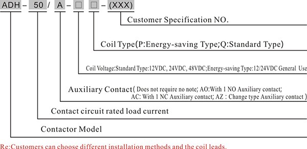
Technical Parameters Electrical specification
| Insulation Resistance | Between Contacts | 1000MΩ(1000VDC) |
| Between Contacts and Coil | 1000MΩ(1000VDC) | |
| Between Contacts and Shell | 1000MΩ(1000VDC) | |
| Dielectric strength | Between Contacts | 4000V rms |
| Between Contacts and Coil | 4000V rms |
| Impact | Stability | 196m/s2(20G) |
| Strength | 490m/s2(50G) | |
| Vibration | 10-500Hz 98m/s2(10G) | |
| Mechanical life | 1,000,000 times |
| Impedance load life(Switch) | 20,000times(50A 450VDC) 20,000times(-50A 450VDC) |
| Capacitive load life(Just closed) | 50,000times(100A 1ms) |
| 60times(250A 1ms) | |
| 10times(400A 1ms) |
| Contact form | 1SH | Leading-out | M4 Internal thread |
| Contact resistance | 0.2mΩ (200A) | Rated load voltage | 12-900VDC |
| Maximum switching surrent | 2000A 320VDC(≥1times) | Maximum switching power | 640KW |
| Rated load current | 200A | Rated Electric life | 20,000times |
| Min Load | 1A 12VDC | Standards for electric current(10mm2Line) | 200A |
| Short time overload current(10mm2@40℃) | 75A 15min,100A 3min,150A 30s | ||
| Parameters | Standard type voltage | |
| 12VDC | 24VDC | |
| Work voltage | 18-32 | |
| Max voltage | 36 | |
| Action voltage | 7-8 | |
| Release voltage | 5-6 | |
| Coil resistance | 4.7 | |
| Min start current(A) | 1.5 | |
| Transient surge current(A) | 2.5(0.1s) | |
| Average holding current(A) | 0.18(@12V) | |
| Steady state Power(W) | 2-2.3 | |
| Actuation time(ms) | ≤20 | |
| Release time(ms) | ≤10 | |
| Bounce time(ms) | ≤5 | |
| Operate temperature | -40℃~85 ℃ |
| Operating Humidity | 5~95%RH |
| IP Grade | IP67 |
| Dimension(W×H×D,mm) | 80.0×64.2×78.7 |
| Weight(g) | 440g |
 Re:
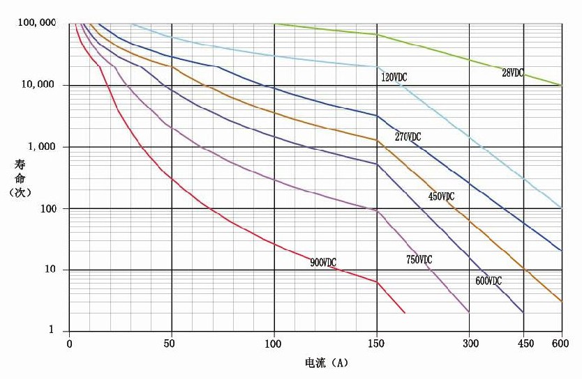
Re:1.Resistive load, including the maximum load inductance300μH;
2. According to extrapolated, it is recommended to do experiments for different situations;
3. After life time, diaelectric strength dropped lower than 100MΩ at 1000VDC;
4. The biggest and current. Coil schematic
 Re:A1, A2 as the load; 1, 2 for the coil end; Load and coil has no polarity. Installation Diagram
 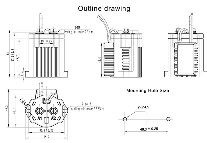 Notes 1. Under the resistance load, the rated parameters of the main contact is applicable. If inductive load is adopted and L/R>1ms, the inductive load need to have an protective unit of inrush current in parallel, and also spare room needs to be considered in the designation. 2. The coil and the contact of the contactor coil need to be continuously charged with electricity when full loaded. The power need to be connected when cut off. Because of the rise of the temperature, the coil resistance is rising, and the pull-in voltage is also risen. The following measure should be taken: lowering the load voltage and limiting the power-on time. 3. The power of drive circuit of the contact coil must be greater than the coil power of the products. Otherwise, the normally usage of high voltage dc contactor will be influenced.
 4. The contactor with energy saving board, when connected after 0.15s, the coil starts to switch automatically. Please do not repeat to turn on and turn off. Otherwise, the contactors maybe broken.
5. Working Life: ADH series contactors are high voltage switch. It may lost its switch function when in the breakdown mode. Therefore, please do not use it when the condition is not suitable to the contactors. When the working life is almost there, please to change it in time in order not to flame the parts around. The circuit diagram should be well-designed in order to switch off within 1 second.
6. Internal Gas and Life: ADH series contactors adopt pressurized cabin contact. The cabin is filled with gas. The life of the gas is decided by the cabin temperature of the contact. Therefore, the environment temperature should be ensured between -40℃ and +85℃.
7. Please do not use it where the magnetic field is high or near the thermal radiation.
8.To ensure the main power line is closest to the terminal of the contactors. The plain washer, spring washer, nut and screw need to be installed tightly. The incorrect connection order may cause serve overheating and the fusion of the insulating layer.
9. In order not to break the products, the tightening torque of the nuts and screws of the contactors needs to be controlled under the following range. (1) Terminals: :
M4 screw (ADH series 50A): 2~3N·m; (2) Mounting Hole:2~3.5N·m.
Please avoid adhering the oil on the terminal.
Please use the following connecting wire. Otherwise, the unusual overheating will be caused:
ADH-50A: nominal area should be above 15mm; Please do not use the contactor when it is dropped unexpectedly or over-shocked. Hot sale products
 Conventional Templa
 Advantages 1. Small Orders Accepted 2. Quality Approvals 3. Prompt Delivery 4. Packaging 5. Price is good 6. International Approvals 7. Other specification can be customized upon different requirements. Energy Saving Type Using in Golf Cart ADH50 50A High Voltage DC Relay
 Send your inquiry to this supplier
Product Alert
Subscribe to your interested keywords. We will send freely the latest and hottest products to your Inbox. Don't miss any trade information.
Your use of this website constitutes acknowledgement and acceptance of our Terms & Conditions.
Copyright © 2009-2024 Bossgoo Co., Ltd. All rights reserved.
