

Sign In Join Free

1 / 1
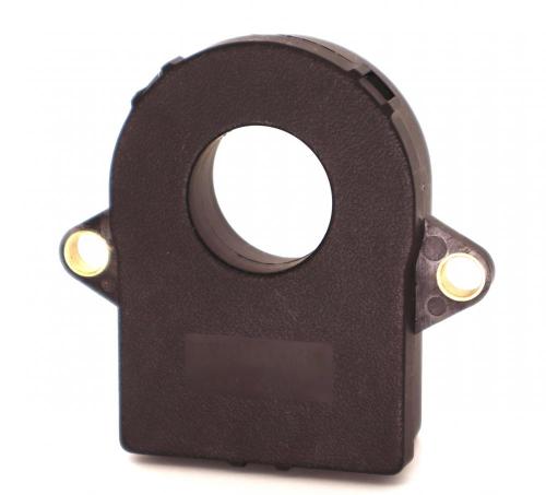
battery testing system fluxgate current sensor DXE-CAB500
| Model No. : | DXE-CAB500 |
|---|---|
| Brand Name : | DEXIE, or OEM service is available |
| place of origin : | China |
Shanghai, Shanghai, China
- Manufacturer
- Trade Company
- Gold Supplier

- Platform Certification

- Online Expo


Product description
Current transducer DXE500CAB IP N = 500 A
The zero bias current is less than 10mA due to the use of a flux gate principle, no hysteresis effect, still present after 1000A high current impact capable of maintaining low bias and high accuracy characteristics.
Especially suitable for high accuracy power battery level monitoring management system applications.
All functions and environmental usage conditions of the sensor meet the requirements of automotive grade level.
Features
● Good linearity-Linearity error<0.1%
● Wide voltage supply-Power supply voltage+11V -+30V
● Power protection function-Overvoltage automatic protection
● Good accuracy-Accuracy: 0.2%-Temperature drift<50ppm
● Digital communication-High speed CAN2.0 interface
● Sensor operating temperature range: -40 ℃ - +105 ℃
Application Domain
● Electric vehicle Battery management system (BMS)
● Electric Vehicle Battery System Distribution Box (BDU)
● High voltage distribution box (PDU) for electric vehicles
● Energy Management of Industrial Lithium Batteries
● Equipment Ground Tank Backup Power
Electrical data
|
Parameter |
specifications |
Condition |
||
|
Minimum value |
Standard value |
Maximum value |
||
|
Rated input IPN= |
-500A |
|
500A |
/ |
|
Measure range IPM= |
-600A |
|
600A |
|
|
Power supply current UC |
11V |
12V/24V |
30V |
|
|
Working current @Ip=0A IC |
|
30mA |
|
Uc=12V,T=25℃ |
|
Working current @I PM IC |
|
160mA |
|
Uc=12V,T=25℃ |
|
Linearity Error L |
-0.001 |
|
0.001 |
±30℃ |
|
Zero deviation @ Ip=0A Io |
-10mA |
|
10mA |
±30℃ |
|
Accuracy @ Ip=± 40A XG |
-60mA |
|
-60mA |
±30℃ |
|
Operating temperature TA |
-40℃ |
|
105℃ |
|
|
Zero temperature drift Toff |
|
0Ma/K |
|
|
|
Gain temperature drift Tgain |
-50ppm/K |
|
50ppm/K |
±30℃ |
|
Output noise |
-10mA |
|
-10mA |
|
CAN Data Format
|
Message Description |
CAN ID |
Data length |
Message launch type |
Signal description |
Signal name |
Start bit |
Length |
|
Return Current IP (mA) |
0X3C2 |
8 bytes |
Cyclic transmitted message 10ms cycle |
IP Value: 80000000H=0mA 7FFFFFFFH=-1mA 80000001H=1mA |
IP-VALUE |
24 |
32 |
|
Error indication 0 = Normal 1 = Failure |
ERROR INDICATION |
32 |
1 |
||||
|
Error Information |
CSM_FAIL |
33 |
7 |
||||
|
NAME |
PRODUCT_NAME |
48 |
16 |
||||
|
CRC-8 POLY: 8+X2+X+1 |
CRC_8 |
56 |
8 |
Error information
|
Error description |
IP VALUE |
ERROR INDICATION |
ERROR INFORMATION |
|
Invalidation error |
FFFFF FFFH |
1 |
40H |
|
Current exceeds 600A |
FFFFF FFFH |
1 |
41H |
|
Overfrequency oscillation exceeding 10ms(>2.5kHz) |
FFFFF FFFH |
1 |
44H |
|
The magnetic ring does not oscillate more than 20ms |
FFFFF FFFH |
1 |
46H |
|
Entering Failure Mode |
FFFFF FFFH |
1 |
47H |
|
No signal exceeding 100ms |
FFFFF FFFH |
1 |
49H |
|
Overvoltage(>32V) |
FFFFF FFFH |
1 |
4AH |
CAN electrical parameters
● CAN2.0
● CAN oscillator tolerance: 0.27%
● Baud rate: 250kpbs
● External resistance: 120Ω
● Data pattern: big-endian
Mechanical characteristics
● General tolerance: ± 0.5 mm
● Other tolerance execution: GB/T 1804-2000-m
● Fixing hole size: Disc installation φ 6.5mm
● Fasten screw: M6
● Recommended fastening torque: 1.8Nm(± 10 %)
● Connector: Tyco AMP 1473672
● Shell material: PBT GF30
● Weight: 80g
● Pin material: tinned brass
● IP GRADE: IP56
Performance parameter definition
● Static output voltage (VQVO): Sensor output voltage in the absence of obvious magnetic field B=0G state
-BR: The static voltage output VQVO has a constant ratio to the power supply voltage Vcc; VQVO= Vcc/
● Sens (sensitivity): Sens is the slope of the reference output line VOUT=VCC/2+2×IP/IP_MAX, which refers to the change in output as the current changes. Its relationship with the current is : Sens=2/IP_MAX
● Zero temperature drift (Off set with Temperature): Due to the tolerances of internal components, stress and heat dissipation factors, the zero point may shift under stable working conditions
● Sensitivity temperature drift (Sensitivity with Temperature): Due to the influence of the internal temperature compensation coefficient, the sensitivity will change over the entire operating temperature compared to the expected value at room temperature
● Zero point electrical offset voltage ( Electrical offset Voltage): The error caused by the noise of HALL components and the amplification factor of the internal operational amplifier itself is called offset voltage
● Response time : The response time of a sensor refers to the time interval between the final 90% of the applied current and the corresponding value of the sensor output to the applied current.
● Zero magnetic offset voltage ( Magnetic Offset): When the primary current reaches its maximum value of IP→0, the error generated at the output end due to the hysteresis phenomenon of the magnetic core material of the sensor is called the zero magnetic offset voltage.
NOTE
● Incorrect wiring may cause damage to the sensor. After the sensor is connected to a 5V power supply, the measured current passes through the direction of the sensor arrow, and the corresponding voltage value can be measured at the output end.
● -BR mode: Zero point output voltage VQVO=VCC/2, Gain fixed at 2V, The output curve is :VOUT=VCC/2+2×IP/IP_MAX;
If the power supply voltage changes within a certain range, it will cause a change in VOUT;
For example, VCC range 4.75V~5.25V, the static output voltage VCC corresponding to 0A has an output range of 2.375V~2.625V, and the gain does not change with VCC, fixed at 2V. Therefore, the output range of full scale VOUT(IPMAX) is 4.375V~4.625V.
-BF mode: Between VCC= 4.75V ~ 5.25V, the zero output voltage is fixed at 2.5V and the fixed gain is 2V. The output curve is: VOUT=2.5+2×IP/IP_MAX.
Shanghai, Shanghai, China
- Manufacturer
- Trade Company
- Gold Supplier
- Platform Certification
- Online Expo
Send your inquiry to this supplier
Product Alert
Subscribe to your interested keywords. We will send freely the latest and hottest products to your Inbox. Don't miss any trade information.
Your use of this website constitutes acknowledgement and acceptance of our Terms & Conditions.
Copyright © 2009-2024 Bossgoo Co., Ltd. All rights reserved.
