

Sign In Join Free

1 / 1
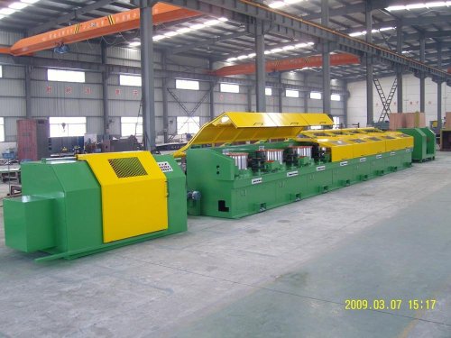
18.5kw Welding Wire Drawing Machine Have Safety Cover With Rubber Sealed Edge


Product description
18.5KW Welding Wire Drawing Machine Have Safety Cover With Rubber Sealed Edge
LZ 8/560 Steel Wire Drawing Machine
Ⅰ. Main parameter sheet:
|
Seq. |
Item |
Unit |
Parameter |
|
1 |
Mode |
|
LZ8/560 |
|
2 |
Drawing method |
|
Tilted drawing blocks |
|
3 |
Number of drawing block |
piece |
8 |
|
4 |
Diameter of drawing block |
mm |
560 |
|
5 |
Speed control method |
|
A.C. Frequency inverter motor |
|
6 |
Power of drawing motor |
KW |
The first block is 22KW, others are 18.5KW (tilted) |
|
7 |
Max. Inlet wire diameter |
mm |
Φ5.5mm |
|
8 |
Min. Final product diameter |
mm |
Φ2.0mm |
|
9 |
Carbon percentage |
% |
0.1% |
|
10 |
Mn/Si percentage |
|
High Mn (1.45%)- High Si (0.8%) |
|
11 |
Max. Machine design speed |
m/s |
20 |
|
12 |
Control system |
|
All digital |
|
13 |
Logic control system |
|
PLC( SIEMENS) |
|
14 |
Cooling system of blocks and dies |
|
Water and ring wind cooling system for blocks, Water cooling system for dies |
|
15 |
Required cooling water supply |
|
0.2~0.3MPa |
|
16 |
Required air supply |
|
0.6MPa |
|
17 |
Time span of machine stop |
second |
Normal≤50s quick≤15s; emergency≤4s (Buyer can set the data) |
Ⅱ. Main description:
1. Illuminating system inside the drawing room. Safety cover with rubber sealed edge.
2. A inside dust-collection pipe net is included connecting the branch flanges. Buyer needs to add one set of dust-exhausting system (buyer's scope) to an outlet connection flange.
3. All drawing blocks are made of alloy steel material with high wear-resistance treatment (Tungsten Carbide). Hard treatment: 200mm height of working surface. Surface hardness: HRC 60-62, roughness 0.8um
4. Harden-Surface Gearbox
5. Grade 1 narrow “V” belt transmission system, the motor power transmission can reach 95%.
Ⅲ. Control System:
1. Main components:
|
Seq. |
Item |
Brand |
|
|
1 |
Inverter |
ABB |
|
|
2 |
PLC & Moulds (password for the user) |
SIEMENS
|
|
|
3 |
Touch Screen |
SIEMENS |
|
|
4 |
Drawing Machine Motors |
China |
|
|
5 |
Low voltage parts |
Schneider |
|
|
6 |
Buttons and indicators |
Schneider |
|
|
7 |
Displacement sensor |
TE France |
|
|
8 |
Power supply: 3P/440V/50HZ(can be set) |
||
2. Main Protection & Error display
2.1. A.C. power-off
2.2. Automatic switch trips
2.3. Over speed and over load protection device for main motors and winding motor
2.4. All VFD faults
2.5. No actions of main contactors in winder and spool stations
2.6. Over or low power voltage( +10%, -10% (no emergency stop)
2.7. Wire break on any spools
2.8. Low air pressure (no emergency stop)
2.9. Emergency stops
2.10. Power-off of fan motor
Ⅴ. Mainly Running Control Functions:
1. All motors run synchronously with matched speed for normal drawing.
2. Each motor can run independently, in continuous or normal/reverse inching turning. A group of motors before or after any special motor of the production line can run synchronously with matched speed.
3. Synchronous running speed is set on main operation console. Separate motor running speed can be set separately, which is useful for starting/ending a drawing process.
4. User may take advantage of wire-break switches (stop/recover the production line running) to handle starting/ending a drawing process.
5. Each motor could be operated near to accordingly spool. Production line can be synchronous-running operated at winder stand and operation console. Inching turning is operated by a pedal switch. The cooling fan of the spool stops during the inching turning.
6. There are emergency stop buttons near every spools, winder, un-winder, and operation console.
7. In stop condition, wire press plates could be pressed on or released manually.
8. Voltage meters, current meters installed on electric cabinets.
9. Display of winder running time on touch screen.
10. Display of all motor speeds, all motor loads and faults on touch screen.
11. Measure and display of the length of wire drawing. Stop setting when the product reaches set length. Alarm setting when the length is near to set length.
12. All cables between control cabinets to all mechanical stands, all labors installing the cables are buyer’s scope. Seller is responsible to the cable connections inside the machine.
Send your inquiry to this supplier
Product Alert
Subscribe to your interested keywords. We will send freely the latest and hottest products to your Inbox. Don't miss any trade information.
Your use of this website constitutes acknowledgement and acceptance of our Terms & Conditions.
Copyright © 2009-2024 Bossgoo Co., Ltd. All rights reserved.
